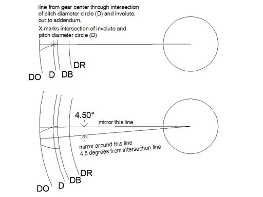
Patent ep2397243a1
Table of Contents
Table of Contents
If you’re a mechanical engineer or enthusiast who loves building machines, then you know how important gears are. They are the critical components that help in transmitting rotational force to different parts of machinery, and there are few gear systems more impressive than the involute gear! In this post, we will show you how to draw involute gear and its related keywords, so you can start building amazing machines of your own.
One of the most significant pain points for many people is not knowing how to start drawing involute gear. With its unusual design and complex geometry, it can be challenging to create an accurate representation of the gear. Not to mention that many online tutorials are hard to follow or poorly explained, making it difficult for beginners to understand.
So, how exactly do you draw involute gear? It is much simpler than you think! You need to start by understanding the basic geometry of the involute and then proceed with the drawing process, layer by layer.
To start with, you need to understand that the involute is simply a curve that is traced by a point on a line that is unwound from a circle. Once you understand the involute curve’s basic concept, you can start drawing the gears layer by layer, starting with the topmost layer and working your way down.
In summary, to draw involute gear, you need to have a good understanding of the involute curve’s basic geometry and then start by drawing each gear layer by layer.
How to Draw Involute Gear - Target
When I first started my journey as a mechanical engineer, I was fascinated by gears and their design. However, I always struggled with drawing involute gear because of its complexity, and I couldn’t find any tutorials that were easy to follow. After many trials and errors, I eventually figured out how to draw involute gear, and I want to share my knowledge with anyone who is struggling with this process.
Understanding the Involute Gear Design Geometry
One of the essential things to understand when learning how to draw involute gear is the gear’s design geometry, the circle on which the involute is formed. The base circle is the size of the pitch diameter of the gear and is usually drawn first. Next, draw a perfect circle of the same size, which becomes the top land for the gear’s teeth. Draw a line through the circle’s center and the base circle, known as the pressure angle line. This line is crucial because it determines the gear’s angle and the tooth profile.
 Drafting Involute Gears
Once you have drawn and set up the gear’s design geometry, the next step is to draft the involute curve. You can draft the involute curve using a variety of methods, including hand-drafting or using CAD tools. However, it is essential to keep in mind that the involute curve should be tangent to the base circle at every point along its length.
 ### Calculating the Involute Curve
Calculating the involute curve’s length is essential, especially if you’re working with large gears. You can use a simple equation or look up a table to determine the length of the involute curve. The length of the curve determines how many teeth will exist on the gear’s pitch circumference.
The Finishing Touch
Once you have drafted the involute curve and calculated its length, the next step is to finish the gear drawing. Add details such as the teeth, the back cone, the clearance, the fillets, and finally, the center hole. It’s essential to make sure that all parts are to size and within tolerance to ensure proper meshing when you start working with the gears.
Q&A
Q. What is the difference between involute and cycloidal gear?
A. Involute gears are the most widely used gear system, while Cycloidal gears are used mainly in specialized machinery. The main difference between the two gears is their shape.
Q. How accurate should my gear drawing be?
A. Gears need to be accurate to within a few thousandths of an inch, so make sure that you follow the instructions accurately.
Q. What CAD software is best for drawing involute gears?
A. Several CAD programs are great for drawing involute gears, including SolidWorks, AutoCAD, and CATIA.
Q. Is it possible to create complex involute gears using only hand drafting techniques?
A. Yes, you can still create intricate gear designs using traditional hand-drafting techniques. However, it would be best to invest in a drafting machine to ensure accuracy and quality.
Conclusion of How to Draw Involute Gear
Learning how to draw involute gear can take some time and effort, but once you understand its basics, you will be able to create the most fantastic machines. So, whether you’re drawing gears for a school project or designing intricate machinery, understanding how to draw involute gear is an essential tool in your arsenal. Keep in mind that the best way to perfect your skills is to practice and to learn from your mistakes. Good luck and happy drawing!
Gallery
Figure 2-0 Involute Circle | Mechanical Engineering Design, Spur Gear

Photo Credit by: bing.com / involute gear spur pt
Patent EP2397243A1 - Form Rolling Method For Involute Gear - Google Patents

Photo Credit by: bing.com / patents involute
Resultado De Imagem Para Involute Gear Design Geometry | Wood Diy

Photo Credit by: bing.com / gears gear involute geometry spur diameter circle autodesk clock pt google inventor gif train 3d
Involute Gears

Photo Credit by: bing.com / involute drawing spline gears standards curves method asa pitch mechanical fig teeth angle pressure machinery chestofbooks practice v2 crafts
The Involute Curve, Drafting A Gear In CAD And Applications

Photo Credit by: bing.com / drawing gear involute spur sketch draw tooth profile curve cad drafting steps pinion rack pitch paintingvalley circle conjugate complementary given


